- 您现在的位置:买卖IC网 > Sheet目录1242 > SFPA32GBQ1BO8TO-I-QT-223-STD (Swissbit NA Inc)FLASH SSD SMART UDMA 2.5" 32GB
�� �
�
�Features� 01h� and� 81h� are� used� to� enable� and� clear� 8� bit� data� transfer� modes� in� True� IDE� Mode.� If� the� 01h�
�feature� command� is� issued� all� data� transfers� shall� occur� on� the� low� order� D[7:0]� data� bus� and� the� -IOIS16�
�signal� shall� not� be� asserted� for� data� register� accesses.� The� host� shall� not� enable� this� feature� for� DMA�
�transfers.�
�Features� 02h� and� 82h� allow� the� host� to� enable� or� disable� write� cache� in� SSD� that� implement� write� cache.�
�When� the� subcommand� disable� write� cache� is� issued,� the� SSD� shall� initiate� the� sequence� to� flush� cache� to�
�non-volatile� memory� before� command� completion.�
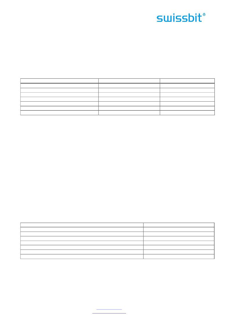
�Feature� 03h� allows� the� host� to� select� the� PIO� or� Multiword� DMA� transfer� mode� by� specifying� a� value� in� the�
�Sector� Count� register.� The� upper� 5� bits� define� the� type� of� transfer� and� the� low� order� 3� bits� encode� the� mode�
�value.� One� PIO� mode� shall� be� selected� at� all� times.� For� Cards� which� support� DMA,� one� DMA� mode� shall� be�
�selected� at� all� times.� The� host� may� change� the� selected� modes� by� the� Set� Features� command.�
�Table� 69:� Transfer� Mode� Values�
�Mode�
�PIO� default� mode�
�PIO� default� mode,� disable� IORDY�
�Bits� (7:3)�
�00000b�
�00000b�
�Bits� (2:0)�
�000b�
�001b�
�PIO� flow� control� transfer� mode�
�Reserved�
�Multi-Word� DMA� mode�
�Ultra� DMA� mode�
�Reserved�
�00001b�
�00010b�
�00100b�
�01000b�
�1000b�
�Mode�
�N/A�
�Mode�
�Mode�
�N/A�
�(1)�
�(1)�
�(1)�
�(1)Mode� =� transfer� mode� number�
�Notes:� Multiword� DMA� is� not� permitted� for� devices� configured� in� the� PC� Card� Memory� or� the� PC� Card� I/O�
�interface� mode.�
�If� a� SSD� supports� PIO� modes� greater� than� 0� and� receives� a� Set� Features� command� with� a� Set� Transfer� Mode�
�parameter� and� a� Sector� Coun� t� register� value� of� “00000000b”,� it� shall� set� its� default� PIO� mode.� If� the� value�
�is� “00000001b”� and� the� SSD� supports� disabling� of� IORDY,� then� the� SSD� shall� set� its� default� PIO� mode� and�
�disable� IORDY.� A� SSD� shall� support� all� PIO� modes� below� the� highest� mode� supported,� e.g.,� if� PIO� mode� 1� is�
�supported� PIO� mode� 0� shall� be� supported.�
�Support� of� IORDY� is� mandatory� when� PIO� mode� 3� or� above� is� the� current� mode� of� operation.�
�A� SSD� reporting� support� for� Multiword� DMA� modes� shall� support� all� Multiword� DMA� modes� below� the� highest�
�mode� supported.� For� example,� if� Multiword� DMA� mode� 2� support� is� reported,� then� modes� 1� and� 0� shall� also�
�be� supported.� Note� that� Multiword� DMA� shall� not� be� supported� while� PC� Card� interface� modes� are� selected.�
�A� SSD� reporting� support� for� Ultra� DMA� modes� shall� support� all� Ultra� DMA� modes� below� the� highest� mode�
�supported.� For� example,� if� Ultra� DMA� mode� 2� support� is� reported� then� modes� 1� and� 0� shall� also� be�
�supported.�
�If� an� Ultra� DMA� mode� is� enabled,� any� previously� enabled� Multiword� DMA� mode� shall� be� disabled� by� the�
�device.� If� a� Multiword� DMA� mode� is� enabled� any� previously� enabled� Ultra� DMA� mode� shall� be� disabled� by�
�the� device.� Feature� 05h� allows� the� host� to� enable� Advanced� Power� Management.� To� enable� Advanced� Power�
�Management,� the� host� writes� the� Sector� Count� register� with� the� desired� advanced� power� management� level�
�and� then� executes� a� Set� Features� command� with� subcommand� code� 05h.� The� power� management� level� is� a�
�scale� from� the� lowest� power� consumption� setting� of� 01h� to� the� maximum� performance� level� of� Feh.�
��Table� 70:� Advanced� power� management� levels�
�Level�
�Maximum� performance�
�Intermediate� power� management� levels� without� Standby�
�Minimum� power� consumption� without� Standby�
�Intermediate� power� management� levels� with� Standby�
�Minimum� power� consumption� with� Standby�
�Reserved�
�Reserved�
�Sector� Count� Value�
�Feh�
�81h-FDh�
�80h�
�02h-7Fh�
�01h�
�FFh�
�00h�
�In� the� current� version� the� adv� anced� power� management� levels� are� accepted,� but� don’t� influence�
�performance� and� power� consumption.�
�Device� performance� may� increase� with� increasing� power� management� levels.� Device� power� consumption�
�may� increase� with� increasing� power� management� levels.� The� power� management� levels� may� contain�
�discrete� bands.� For� example,� a� device� may� implement� one� power� management� method� from� 80h� to� A0h�
�and� a� higher� performance,� higher� power� consumption� method� from� level� A1h� to� Feh.� Advanced� power�
�management� levels� 80h� and� higher� do� not� permit� the� device� to� spin� down� to� save� power.�
�Swissbit� AG�
�Industriestrasse� 4�
�Swissbit� reserves� the� right� to� change� products� or� specifications� without� notice.�
�Revision:� 1.00�
�CH-9552� Bronschhofen�
�Switzerland�
�www.swissbit.com�
�industrial@swissbit.com�
�P-120_data_sheet_PA-QxBO_Rev100.doc�
�Page� 55� of� 76�
�发布紧急采购,3分钟左右您将得到回复。
相关PDF资料
SFPK-SL
CONN SFP CAGE
SFSA16GBV1BR4TO-I-QT-226-STD
FLASH SLC UDMA/MDMA/PIO 16GB
SFSA32GBQ1BR8TO-I-QT-226-STD
FLASH SLC UDMA/MDMA/PIO 32GB
SFSA32GBU1BR4TO-I-NC-216-STD
FLASH X-200M SLC MSATA 32GB
SFSA32GBV1BR4TO-I-NC-216-STD
FLASH X-200S SLC SLIM SATA 32GB
SFSA64GBQ1BR8TO-I-NC-216-STD
FLASH SSD UDMA IND 2.5" 64GB
SFSO4404NR
FEMALE SCREWLOCK 4-40 .197"
SFW22R-1STE1
SFW22R-1STE1-FFC/FPC CONN
相关代理商/技术参数
SFPA32GBQ1BO8TO-I-QT-243-STD
制造商:SWISSBIT NA INC 功能描述:FLASH
SFPA36AT0250
制造商:General Electric Company 功能描述:SFP 3P 600V 250A
SFPA4096Q1BO2TO-C-DT-243-STD
制造商:SWISSBIT NA INC 功能描述:FLASH
SFPA4096Q1BO2TO-I-DT-223-STD
功能描述:FLASH SSD SMART UDMA 2.5" 4GB RoHS:是 类别:计算机,办公室 - 元件,配件 >> 固态硬盘驱动器 系列:P-120 标准包装:1 系列:- 存储容量:64GB 存储器类型:闪存 - NAND 其它名称:VL 64 GB SSHD KITVL64GBSSHDKIT
SFPA4096Q1BO2TO-I-DT-243-STD
制造商:SWISSBIT NA INC 功能描述:FLASH
SFPA-53
制造商:未知厂家 制造商全称:未知厂家 功能描述:Schottky Barrier Diodes
SFPA-63
制造商:SANKEN 制造商全称:Sanken electric 功能描述:Schottky Barrier Diodes (Surface Mount) 30V
SFPA-73
制造商:未知厂家 制造商全称:未知厂家 功能描述:Schottky Barrier Diodes